So I have a bit of an obsession with making things as small as possible (google TinyPi Pro) and its all too easy to get down a rabbit hole of zooming in like crazy on the CAD and before you know it you have details that are 0.5mm and beyond the capabilities of ‘normal’ 3d printers.
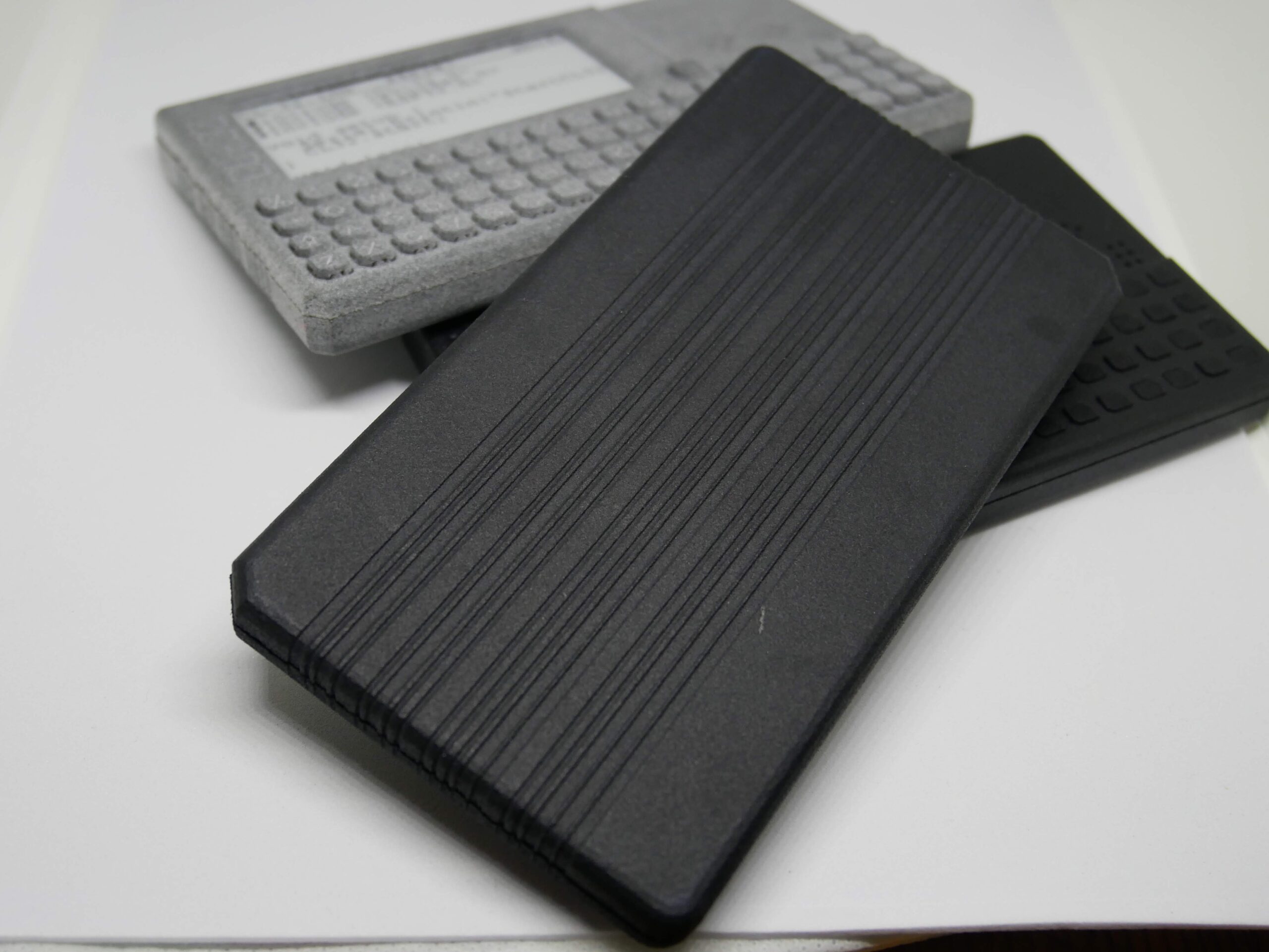
I had assumed that was the case here too, my early test prints came out as rough as a badgers bottom!!! The MJF prints that i have been getting are beautiful quality but can mount up the cost if your trying to tweak a design.
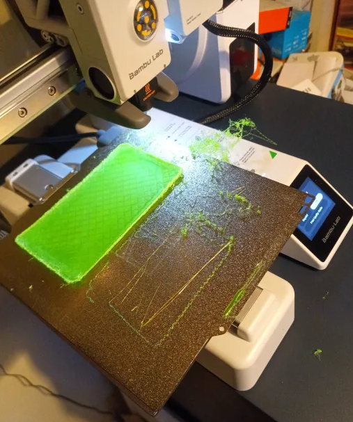
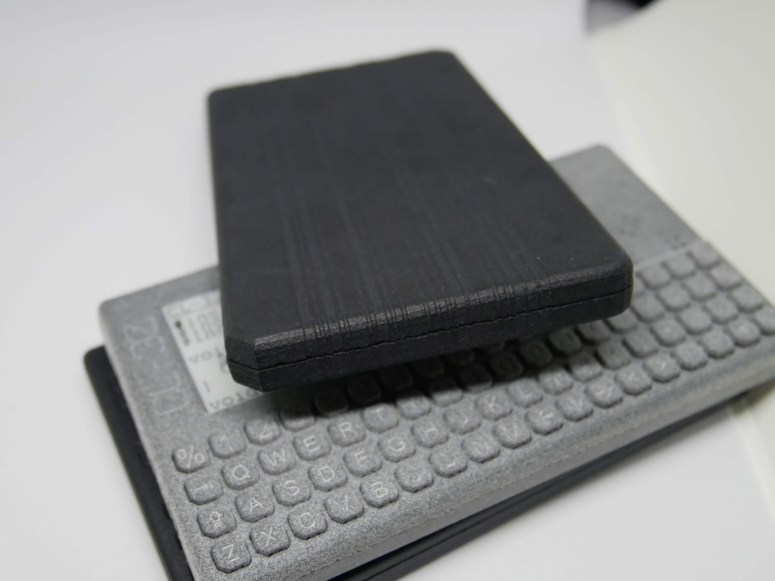
I have just splashed out on a new 3d printer, so I thought lets test this puppy, and cranked the quality all the way up to 11 (actually 0.08mm) and tried to print a case….
not the best start!!! some of the finer details on the case back and all those cutouts on the front mean there isnt really that much plastic actually touching the bed from that first layer. so it started to come away, and the front of the case actually pinged off, all a disaster!!
So after a regroup, I tried on normal quality settings, and added a brim to increase the contact point, and bingo bango we have a winner!!
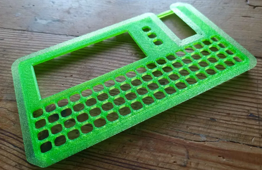
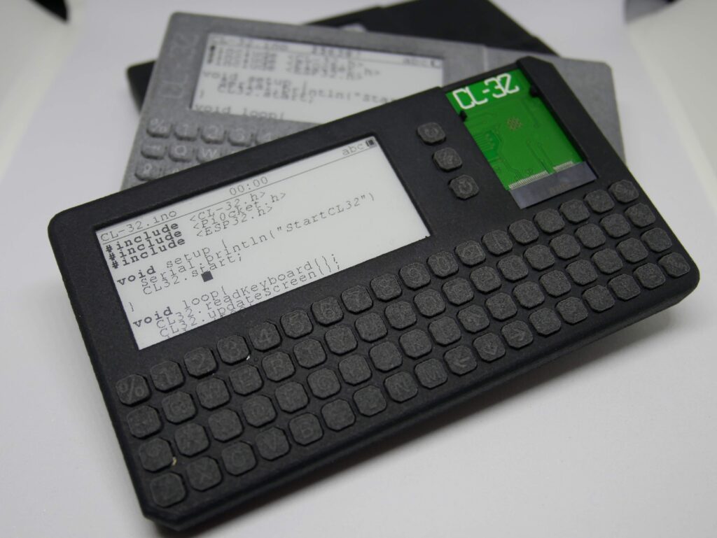
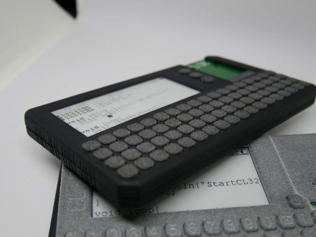
the quality is actually fine. I have tried to design things so that they would be easy to transition to injection molding if a big crowdfunding campaign were to happen, so the way the case splits down the middle and the openings for the ports are all nicely on a top edge of each case half, so FDM manages that fine!
The result is an eye popping case which actually doesnt quite feel as premium as the MJF printed case, but is very very usable
So after my last post about the latch, someone over on Twitter (im not calling it X) said that it would be fun to make it work like a GameBoy power switch. For anyone unfamiliar the sliding action of the switch locks the cartridge in place.
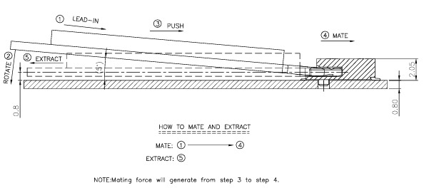
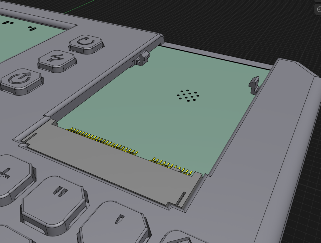
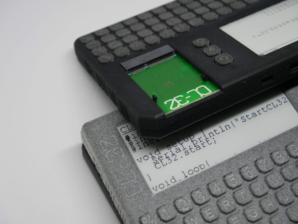
I had a bit of a play with the CAD to see how that would work, and it might be possible. The latch would be on the thin side though, so I thought I would check the datasheet for the M.2 socket and see how it works
Unlike the normal M.2 sockets I have come across in the past, once the card is slid fully into the socket, it no longer wants to jump upwards, and so that changes the way of thinking for the latching method.
Im actually thinking that for small and light boards (like LED’s or sensors, etc) would be fine with just the grip of the M.2 socket. Anything like a LoRa board with an antenna or such might need something to stop it coming out (in the direction of 5)
I think its time to get some of these add-on boards routed and ordered and see how it pans out.
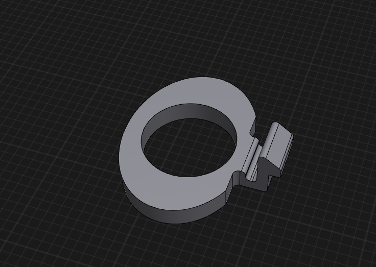
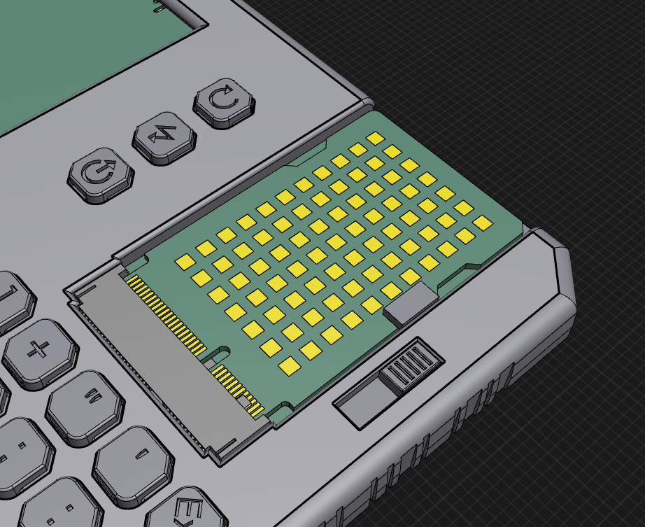
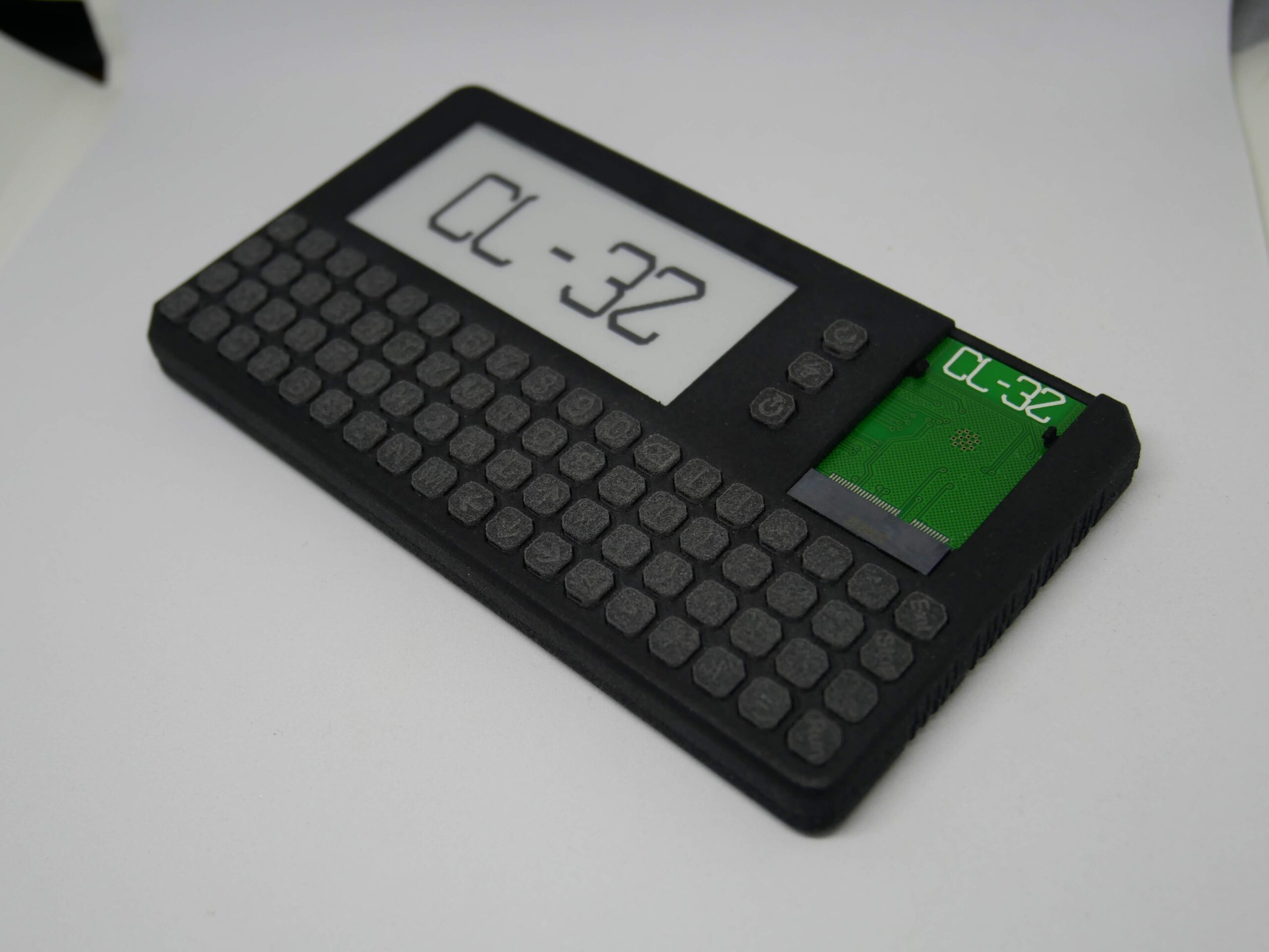
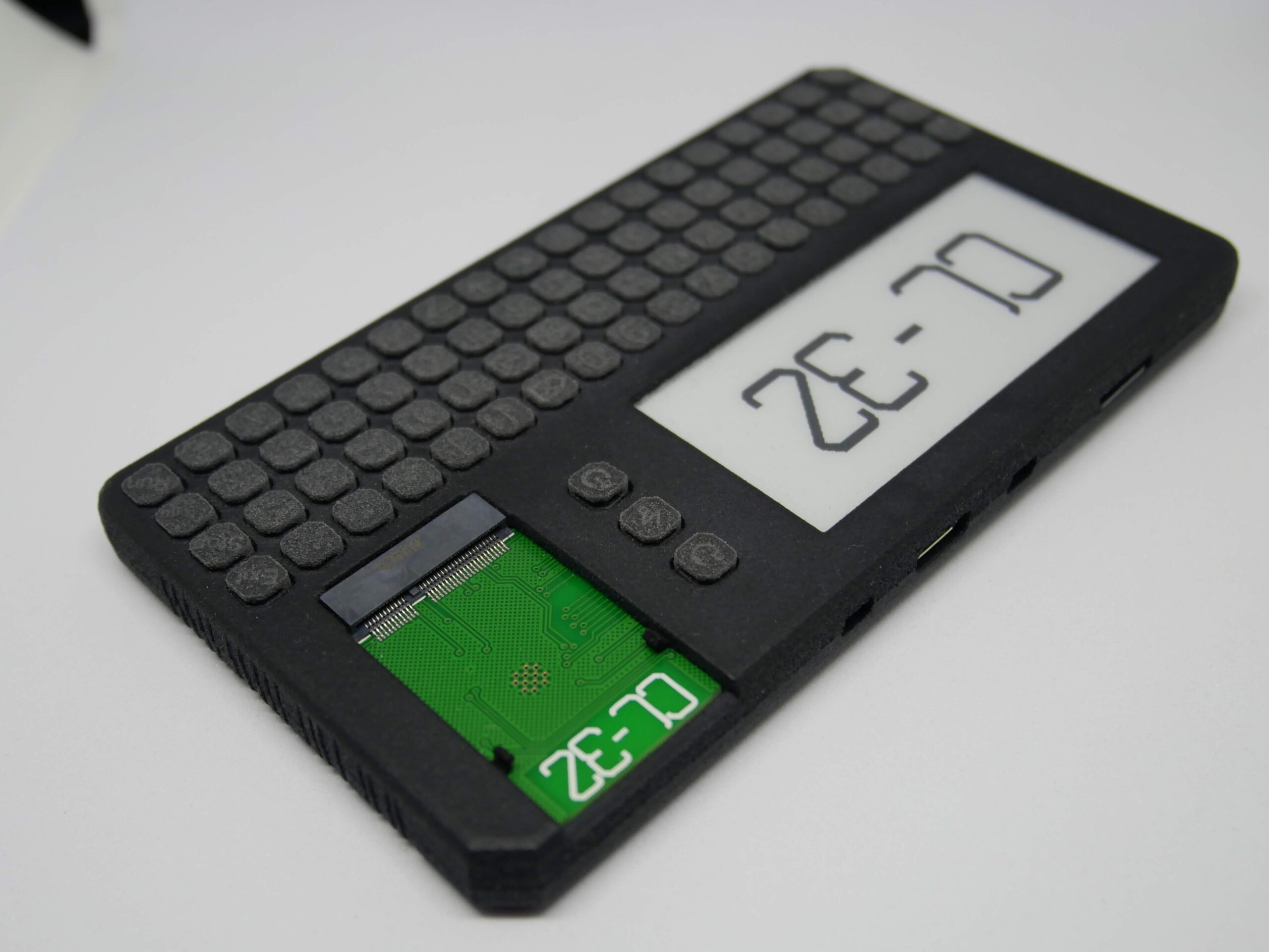
So i want the add on boards to be able to be swapped without tools. The normal method of securing M.2 cards is with a screw, but that is easy to loose, and needs a small screwdriver which can be fiddly.
My original plan was to have some little clips which would hold the board in place. The clips would be removable and replaceable in case of damage.
The clips were included with in the last print, and they sure were small!! I wanted to get the mounting system sorted before spending too much time on the add on boards themselves, so i printed a dummy board for testing (please excuse the fuzzy photos)
While the clips do work, they are super hard and tricky to unclip.
So with some thinking happening, I have come up with another plan
The add on board would of course need to be tweaked to move the cutout to suit, but i think it might be a better solution
Might need some more thought/polish, but its already looking like a better solution…
Soooo, the latest public events might make some folks want to take a break from social media. Im not going to get involved in the discussion about the events, but I am going to change things a little bit to make it so that you dont need social media to get the latest news.
I am going to change the current mailing list to be a weekly update to give you all the inside scoop. I will also make another mailing list for the big news, like release information and such, that way you can stay informed without the weekly updates.
I will still post on the socials too. As much as I dislike it, it really is a useful tool to spread word about the project, and get as many people as possible interested 😊
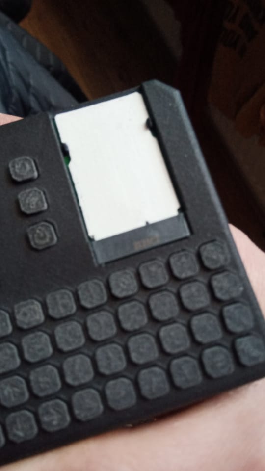
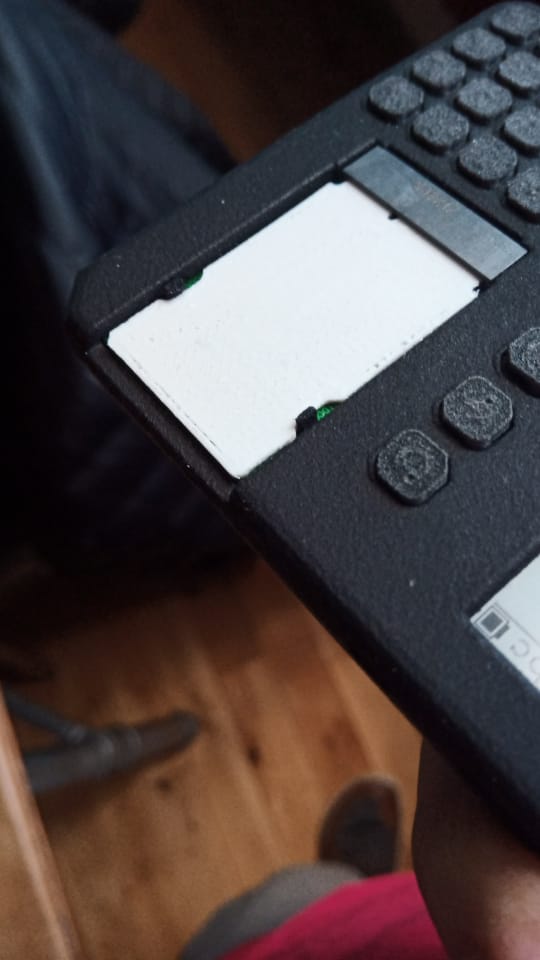
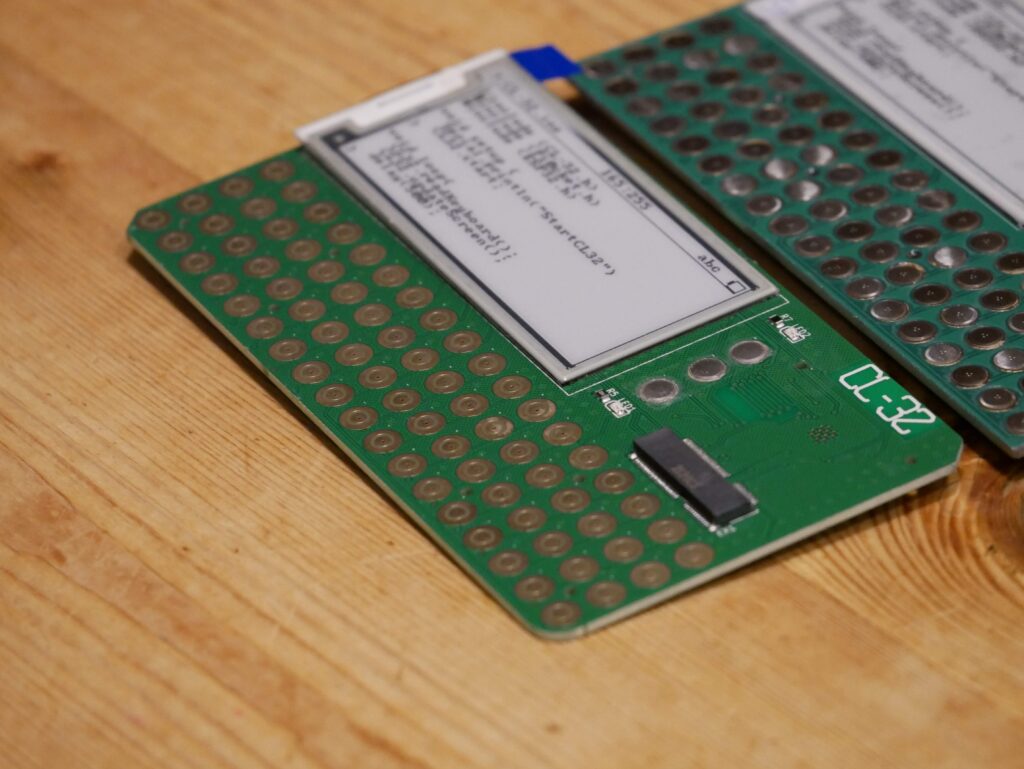
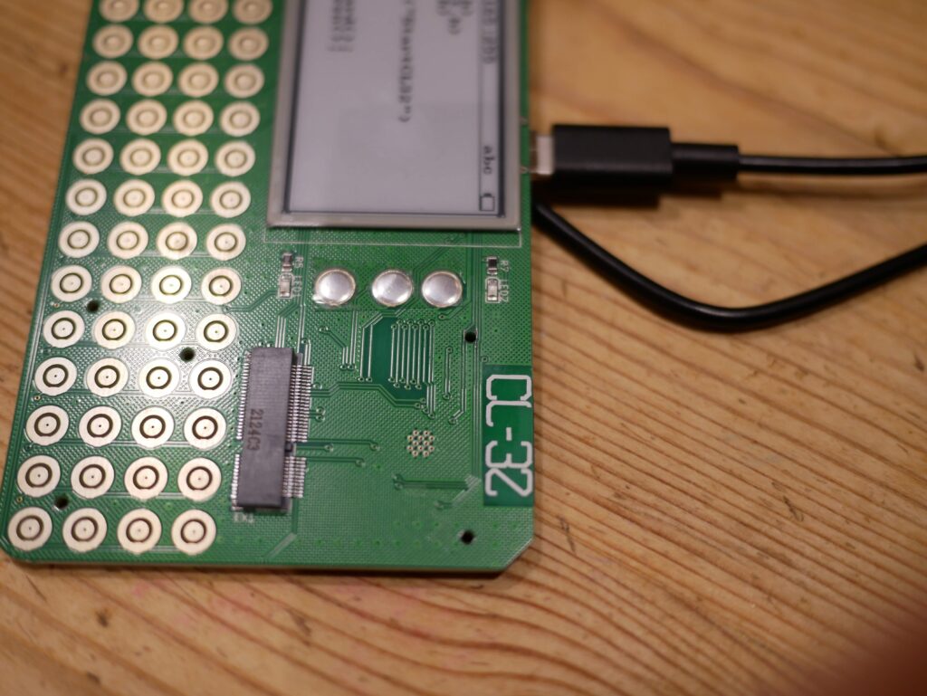
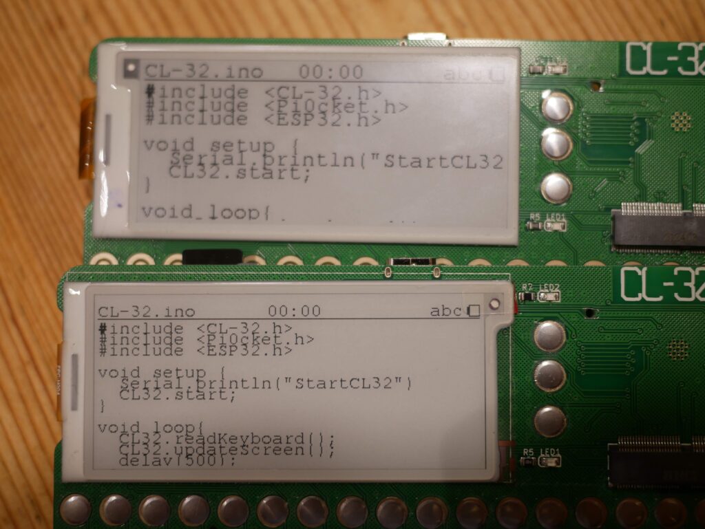
So v0.2 is mostly good. The boards have a few little flaws, but nothing that stops them being usable. Here is the ‘snagging list’
2 traces were a touch too close to one of the mounting holes, and so became broken during manufacture
one of the RTC pins was left floating, (didnt RTFM) stopping it switching over to backup power and so loosing the time when you power off the device
The screen connector is a bit too low for the higher resolution screen (they have slightly different shaped ribbons)
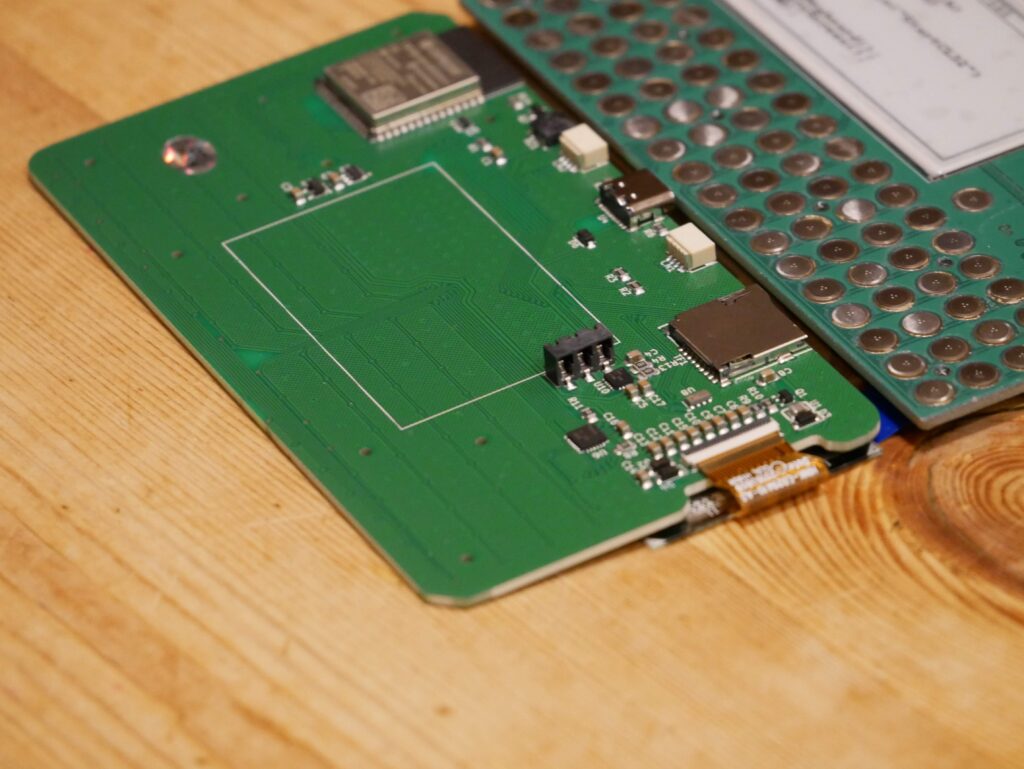
I still need to check the STEMMA/QWIIC connectors, but i dont see any reason they wouldnt work
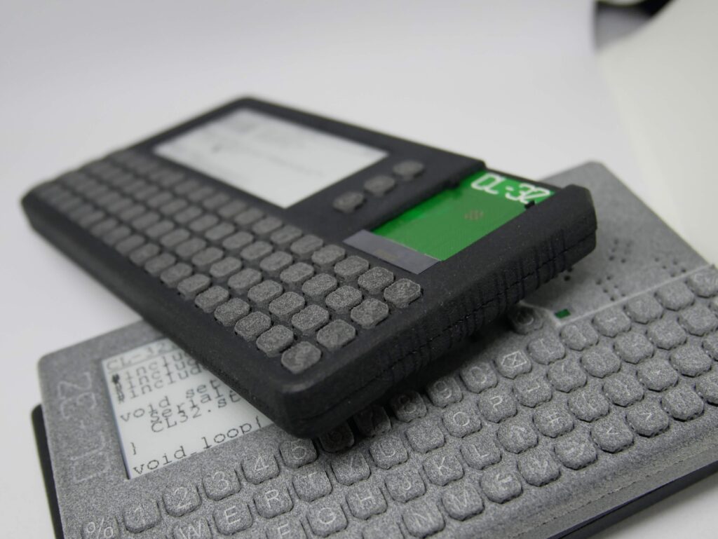
The case has been tweaked to match the new PCB. It has been flipped round from last time, and so the PCB screws to the front of the device to endure that the keyboard is as rigid as can be. There is a new piece which attaches to the back of the PCB in order to hold the battery in place, as well as adding a bit more strength. The back of the case snaps on so that there are no visible screws.
I have made an attempt at a mounting system for the add-on cards so that they can be added and removed without the need to tools. This turned out to be a little small, and so will need another look. Here is the ToDo list for the case
The back of the case was a little loose. I think this might be down to the shotblasting process that is done on the MFJ printed case. This needs some investigation
The battery holder is a little short, and needs a slight tweak to make the battery fit nicer
The STEMMA/QWIIC sockets need more clearance round them. I neglected to consider the size of the plugs!!
The add on board clip system needs a re-design to make it less fiddly and more robust
As with the PCB, there isnt anything ‘show stopping’ but it all needs fixing
So the site has had a little bit of a re-vamp. The information about the device has been spread all over the place so I decided to get things all in one place
I have started to pad out the plan for the device in regards to specifications, software, and the add on system
If anyone has any ideas or suggestions then feel free to drop me a line hello@cl-32-com
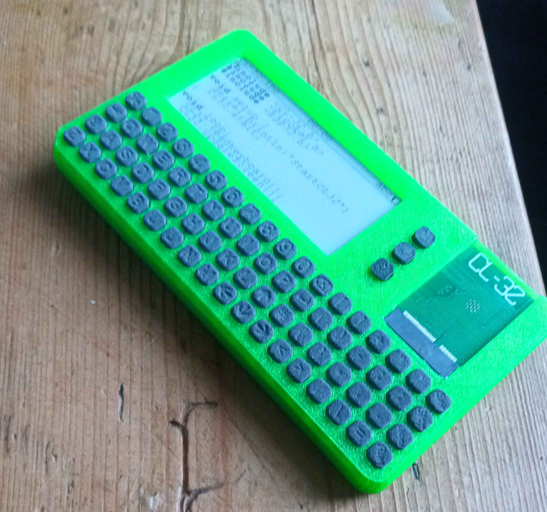
So this just started as a crazy idea, slap a screen and some buttons on a PCB, turn it into a pocket computer. The original had a pi zero for brains.
While having a full linux OS in your pocket can be handy, it also has some drawbacks. First off, your waiting for it to start up before you can do anything useful, which can get really annoying as the pi doesnt have any sleep mode, so a quick session is always bracketed with a startup and shutdown delay. Also the power you get, needs feeding!! Even a reasonable battery will only get you a handful of hours use, and if your working in many short sessions, that can be mostly wasted with the undesirable system usage.
So how much power do you really need??
Well that mostly depends on what you want to use your pocket computer for. You don’t have to look very far back in history to find a chunk of handheld computers that were really popular.
Lets take a look back at an early TRS-80 from 1980 for example, that came out with a 4 bit processor rocking a blistering 256KHz, and 1.5KB of RAM. Coupled with a 1×24 character lcd display, the device allowed programing on the go, and could even interface with other devices like tape storage and printers!!! This was one of the earliest pocket computers and opened up a world of coding on the go
If we go a few years newer, and you come up to devices from Psion. A series 5 is a bigger step up, you gain much in specs, with a 32bit processor running at a mind bending 36MHz, and 16MB of RAM. The screen gains some resolution too, with a 640×240 pixel LCD display adding more space for activities. There was a serial interface again, allowing communication with external devices to increase usefulness
What about the screen??
Sure, it would be nice to have a fancy crisp IPS screen with lots of colours and pixels, but that then increases the demand on the CPU when doing the basic things like editing the code and showing user menu’s etc. Also most screens can be difficult to see in bright situations, such as a bright classroom or outside. Also the backlight on the screen will eat up some of the precious battery
LCD gives better readability when its bright, but then you struggle to be able to see the screen when the device is used in darker conditions. This then means you need a backlight again, so that’s back to eating battery again
e-ink gives you a screen that looks like printed paper, which is readable in almost any environment. This does come with a big drawback that the screen takes a while to refresh, sometimes up to 3 seconds, which wont really work for editing code. There may be ways round that with fast refresh and partial refresh to allow for more usability
How big should it be??
You ask a photographer which is their best camera, and they will tell you its the one they have with them. I think this rings true with anything. Having a device in your pocket will mean that you will use that device. We therefore cant make the device too bit, or it wont really be something you can easily take with you. That means the device needs to be compact, so you cant have a fancy mechanical keyboard and a 12 inch screen
What about the battery??
In keeping with the size requirements, the battery needs to be carefully selected to balance the capacity and size. It is also a good idea to use a standard battery that is easily replaceable by the user. These batteries are also available in reasonable capacities 900-1500mah which would allow for really long runtimes with such a modest CPU and screen